In this section:
Warning Codes
Error Codes
Clearing Errors
Firmware Commands
(general, error handling, configuration, shutdown)
System Messages
Serial Output Explained
LED Status Indicator
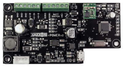
The XAXXON POWER LiPO3S System Power Battery Management Board charges a 3 cell LiPo battery, allows continuous system up-time while switching back-and-forth between wall power and battery, and provides real-time statistics on individual cell voltages and current draw.
The firmware employs fairly strict error checking, to enhance battery longevity and safety. If an error condition is detected, the board will print a code to the serial output. The error codes can be broken down into the categories ‘warning’, and ‘error.’ If the firmware detects an ‘error’ category error it will also disable or limit charging until the code is cleared manually. (See the clearing errors section below). Codes 80+ are the most severe and require that wall power be removed.
If running this PCB on board a Xaxxon robot, any current and past warning and error messages will be displayed in the remote web browser interface.
NOTE: Errors and warnings are reported as a historical list, so a code will be listed even if the condition that caused it is no longer present.
For specifications and further info see the Xaxxon POWER v2 PCB product page
Warning Codes
HIGH_CURRENT_SHUTDOWN – code 2
This occurs if the battery drain exceeds 4.25 amps, which is getting close to blowing the 5A fuse. All system power is immediately shut down.
If the PCB is on board a Xaxxon robot, this typically happens if one or more of the wheel motors are stalled (at 3.75 amps the java application turns off the motors automatically, but this error still may be thrown if the reaction isn’t quick enough).
NO_BATTERY_CONNECTED – code 3
Occurs if no battery is plugged in
WALL_BRICK_LOW_VOLTAGE – code 4
Occurs if the incoming wall power voltage goes below threshold. If the PCB is on board a Xaxxon robot, this is sometimes caused by a misaligned dock connection, and the system will automatically attempt re-docking. If this error persists and re-docking is common, make sure the wall power adapter plugs are securely attached, and try unplugging the adapter from the wall momentarily
OVER_DISCHARGED_PACK – code 5
Occurs if one or more battery cells drops below safe voltage. It could have been only for a few seconds, but under-voltage situations can cause internal cell shorts and off-gassing; it is a good idea to check the pack for excessive swelling. Charging will occur at a reduced current until the cells are within safe voltage range
PACK_DRAINED_TO_ZERO_PERCENT – code 6
Occurs if the battery is drained completely (but still within non-cell-damaging levels). The battery should typically be kept topped up to maximize longevity
MAX_PWM_BUT_LOW_CURRENT – code 21
NOTE: was code 42 in firmware versions 0.23 and earlier.
Occurs if little or no current is detected flowing into the battery when charging. Check that the main BATT SWITCH toggle is turned ON, or check for fuse F1 continuity (if the fuse is blown a replacement 5A fuse can be wired into JP2). Charging is disabled.
Error Codes
SEVERELY_UNBALANCED_PACK – code 41
Occurs if individual cell voltages differ beyond an acceptable range, usually indicating a faulty or damaged pack. Charging is disabled
OVERCHARGED_CELL – code 43
Occurs if voltage of one or more cells are detected above safe range, usually indicating a faulty or damaged pack. Charging is disabled
REGULATOR_CANT_FIND_TARGET – code 44
Occurs when the target charging current can’t be reached; could be caused by an under-powered wall power adapter and/or a heavy system power draw. Charging is disabled
UNABLE_TO_COMPLETE_CHARGE – code 45
Occurs if the battery fails to accept charge; could be caused by faulty or damaged pack. Charging is disabled
CHARGE_TIMED_OUT – code 46
Occurs if the battery fails to complete charging within the allotted time, could be caused by faulty or damaged pack, or by packs greater than 6Ah capacity. Charging is disabled
POWER_SOFT_SWITCH_FAIL – code 61
Occurs if the ‘r’ or ‘powershutdown’ command fails to kill all power to the system. Charging is limited to low voltage
EEPROM_ROLLOVER – code 62
Occurs if warning and error codes fill the entire eeprom, potentially losing error history (and ability to diagnose problems). Charging is limited to low voltage
CURRENT_OFFSET_TOO_HIGH – code 81
Occurs if the current sensor is reading incorrectly, possibly due to a faulty or damaged sensor. Charging is disabled, and wall power needs to be removed.
If the PCB is on board a Xaxxon robot, the system reacts to errors 80 and higher by un-docking and disabling future docking)
UNEXPECTED_CHARGE_CURRENT – code 82
Occurs if current is detected flowing into the battery when not intending to charge, indicating potentially faulty or damaged circuitry. Charging is disabled, and wall power needs to be removed. If the PCB is on board a Xaxxon robot, the system reacts to errors 80 and higher by un-docking and disabling future docking)
CONSISTENT_OVER_CHARGE – code 83
Occurs if charging current is higher than expected for extended time, possibly due to faulty or damaged circuitry. Charging is disabled, and wall power needs to be removed. If the PCB is on board a Xaxxon robot, the system reacts to errors 80 and higher by un-docking and disabling future docking)
NO_COMM_WITH_POWER_PCB
Only shown if the PCB is on board a Xaxxon robot, and the system had communication with the Power PCB but lost it, potentially due to a faulty USB connection.
Clearing Errors
WARNING: Codes 40 and higher require the error to be cleared manually, before resuming normal operation. This is a normal step in troubleshooting, to see if the problem persists – BUT you should only clear errors as long as you understand what the original errors were, and are now physically present and closely monitoring the hardware.
Always feel free to contact us so we can help troubleshoot!
The single-byte firmware commands related to errors are:
s (lower case) – Print all error codes
B (upper case) – Clear all error codes only if all warning only
C (upper case) – Clear latest single warning code
4 – Clear all error codes
If the PCB is on board a Xaxxon robot, continue reading below for instructions on using the remote web browser interface to submit error clearing commands. Otherwise,
See the following Firmware Commands section for more info on how to submit these commands.
To clear errors, from within the robot remote web browser interface go to ‘menu’ > ‘advanced’ > ‘telnet text command’ and enter:
powercommand 4
This sends the single byte ‘4’ to clear the all error history from the eeprom. Then enter:
powerreset
to reset the board.
If the error state contains a code higher than 80, you’ll have to clear the ‘force undock’ state in the java server application. Either restart the application, or enter the command:
state delete forceundock
Firmware Commands
Most firmware commands are single byte character commands that can be sent through a serial-over-USB terminal program such as the Serial monitor in the Arduino IDE. However some commands require one or two byte integers following the initial character, which may require a few lines of code to do the conversion.
If the PCB is on board a Xaxxon robot, from within the web browser remote interface you can send commands directly to the board using the telnet command powercommand. To view the board’s response/output, check the ‘oculusPrime/log/power.log’ file. The java code handles the integer-to-bytes conversion in the case of commands that have numbers following.
CAUTION: entering the wrong command can adversely affect the board’s operation and cause damaging situations. Resetting the board can fix most situations (power cycle or issue telnet command ‘powerreset’)
To enter a command, go to 'MENU > advanced > telnet text command' and enter:
powercommand command
Where command is one of the following (case sensitive):
GENERAL COMMANDS
x (lower case)
Report board ID string
7
Report firmware version
A (upper case)
Force write current battery mAh remaining to eeprom (firmware automatically saves battery level every 5 min, but using this command prior to a board reset will help with life gauging accuracy)
ERROR HANDLING COMMANDS
s (lower case)
Read error code history
B (upper case)
Clear all error codes only if all warning only
C (upper case)
Clear latest single warning code
4
Clear all error codes
CONFIGURATION COMMANDS
6
Report battery capacity mAh.
5 {INT}
Set battery capacity, 2 byte integer mAh (stored to eeprom, default 4250)
Note: capacity is adaptive, and is automatically re-calculated and set whenever the pack is drained to 3.5V minimum cell voltage
S {INT} (upper case)
Sets float (ie., charged) voltage per cell, 2 byte integer centivolts (stored to eeprom, default is 415, accepted range is 380-415)
T (upper case)
Report float voltage in volts
E (upper case)
Report dock voltage, volts
D {INT} (upper case)
Set dock voltage, 2 byte integer millivolts (stored to eeprom, default 14000). This sets the minimum voltage from wall power adapter to set ‘docked’ status. Threshold for WALL_BRICK_LOW_VOLTAGE errors is set at 0.6V less.
CAUTION: too low of a setting can cause excessive heat build up at robot dock contacts, should typically be 1.0V less than nominal wall brick voltage.
F {INT} (upper case)
Set current mAh remaining, 1 byte percentage (0-100)
G (upper case)
Report safe current amps
H {INT} (upper case)
Set safe current, 2 byte integer milliamps (stored to eeprom, default is 4250). Battery current drains above this will cause immediate power shutdown. Warning current level (causing motor stop) is 500mA less.
CAUTION: tampering with this setting can cause blown fuse or damage to system.
8
Erase entire EEPROM (warning: this will set battery capacity to default, erase all error code history, and set dock voltage, current calibration, and safe current to defaults)
SHUTDOWN COMMANDS
r (lower case)
Shut off power from battery immediately. Only works if NOT connected to wall power.
Restore power using off/mom switch at JP3, or applying wall power
I (upper case)
Change battery shut off command mode to kill system power out AND microcontroller. This is the default state set on board reset
J (upper case)
Change battery shut off command mode to only kill system power out, leave microcontroller alive
t (lower case)
Restore battery power to system. Only applicable if J command used previously
p (lower case)
Warn host system that battery shut off is pending (ie., outputs “shutdown” to serial), Battery power is shut off within 2 seconds, unless w command is received within that time
w (lower case)
Confirm host system shutdown “shutdown” message received, increases shutdown timer to 30 seconds (to allow for graceful host OS shutdown)
K {INT} (upper case)
Leave microcontroller alive and shutdown battery power to system only, for 2 byte integer seconds (max 65535 seconds / 18.2 hours)
System Messages
The PCB periodically outputs the following system messages, some of which are important to react to for battery safety reasons. NOTE: system message output is typically surrounded with “<>” braces
reset – indicates the microcontroller has just reset and is initializing
redock – indicates low voltage dock connection, re-docking recommended. The Oculusprime Java application reacts to this message by un-docking and re-docking the robot (failure to do so could result in overheating of contact points)
charged – charge complete
docked – dock status detected
undocked – un-docked status detected
wallpower – wall-power connection detected (system typically outputs ‘docked’ status after a short delay, unless the connection is inadequate, in which case the Oculusprime Java application reacts by backing the robot up and trying docking again)
shutdown – power will be cut to system after a short delay (if the host system immediately responds with a ‘w’ command, the delay is lengthened, allowing time for graceful OS shutdown)
power_error {CODE} – error or warning
high_current – high current drain detected. Oculusprime Java application responds to this by stopping motors
Serial Output Explained
The PCB outputs a long status string every few seconds to the serial connection. If running this PCB on board an Oculus Prime robot, this is appended to the power log file (‘oculusPrime/log/power.log’)
Example:
docked 18%_charging cells:3.76_3.77_3.77_idle:3.74_3.77_3.75_sh:000_
sCV:13.61_sIV:14.26_pwm:158_amps:1.01_mAh:989_lV:11.26_cC:0.05_eR:0
Breakdown:
docked 18%_charging – General status
cells:3.76_3.77_3.77 – Individual cell voltages
idle:3.74_3.77_3.75 – If charging active, individual cell voltages between charge pulses
sh:000 – If charging, indicates which balance shunt resistors are active (for each of 3 cells, ‘1’ indicates active, ‘0’ indicates inactive)
sCV:13.61 – If charging, indicates total pack voltage during charge pulse
sIV:14.26 – Indicates total pack voltage between charge pulses
pwm:158 – Charge current regulator duty cycle value
amps:1.01 – Current to/from battery (negative value indicates battery draining, positive indicates charge)
mAh:989 – Estimated battery mAh remaining
lV:11.26 – Latest recorded pack voltage when battery draining
cC:0.05 – Current sensor calibration offset
eR:0 – Current error code
Led Status Indicator
The red LED (LED6) has the following states:
Off – Battery not charging
Steady On – Battery charging
Steady Flash – Error
Periodic pulse (Short flash every 1.5 seconds) – Low battery