Battery Charging and System Power Management Board
The XAXXON POWER v2 System Power Battery Management Board powers Xaxxon mobile robots, and can also provide battery powered mobility for a wide variety of x86/ARM system boards and motherboards. It allows continuous system up-time while switching back-and-forth between wall power and battery, and provides real-time statistics on individual cell voltages and current draw via USB interface.
This board is the next generation of the original Xaxxon Power LiPo3S PCB.
|
Each
US $55.00
|

|
Part No.: XAX-080
In stock
The board is ideally to be used while connected with a host PC (eg., a Xaxxon robot), to take advantage of statistical output, react to messages and errors, and send commands. However, it will operate perfectly in stand-alone mode as well.
Standard Functions:
- Detect wall power and start charging and balancing battery cells, stop charging when full
- Provide wall power or battery power to system +V-S out, depending on availability, seamlessly without interruption
- Monitor current draw -- if dangerously high current, output warning message, and/or power down system
- Soft shut down (firmware/MOSFET controlled) all power output from battery if pack depleted, to avoid battery damage (function can also be used as convenient general power down)
- Optional soft shut down battery power to system +V-S out only, while leaving microcontroller alive, returning system power after specified delay
- Tally amps in and out over time, to estimate battery life remaining, and re-evaluate pack capacity periodically
- Continuously output system statistics, including individual cell voltages, wall power voltage, current draw, and PCB status
- React to error conditions and faulty packs by outputting messages, storing error history, and disabling/limiting charging if necessary
Enhancements to previous generation PCB include:
- No parasitic battery drain
- Allows daisy-chaining of multiple boards and batteries for increased capacity
- Added second soft power shutoff mode: can now kill system power only, keep 5V microcontroller alive, optionally bring system power back up after specified delay
- Optional isolated battery-only power out (eg., for 12V motors to never experience high wall power voltages)
- Higher wall power voltages accepted, up to 20V
- Protection diode and 5A fuse now on-board
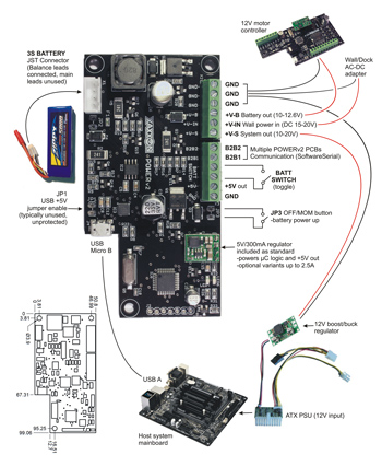
Example Setup/Typical Wiring Diagram:

|

|
Specifications/Details:
- 10-20V system power out (max 3A continuous/5A peak)
- DC wall power in: 15-20V nominal (14.5 minimum, 20.5V absolute maximum)
-4A minimum
-System boards, including ATX & Mini-ITX systems should have compatible wide input power capability, or use a suitable boost/buck DC-DC regulator
- Battery only 10-12.6V power out (max 3A continuous/5A peak)
-Current limitation (and all PCB circuitry/safety features) can be bypassed by connecting load directly to main heavy gauge pack leads, instead of using balance connector only
- Accepts 3 cell (11.1V) Lithium Polymer battery (Turnigy, Zippy, Turnigy-Graphene brands tested)
- Integrated charging at 1.0Ah nominal
- Charging at 0.3A max conditioning current if highly depleted pack
- Individual cell balancing
- JST-XH balance connector (4 pin for 3S battery)
- Battery in/out current monitoring (hall effects sensor)
- Precision voltage reference, individual pack cells and system power
- Atmel ATMega 328P microcontroller
- USB serial interface, micro-B female USB connector
- Battery power shut off function (firmware/MOSFET controlled)
-Low battery safety auto system power shutoff
-Optional leave microcontoller 5V circuit alive only
-NOTE: does not shut down +V-B terminal
- Integrated 5A fuse
- Integrated protection diode on wall power +V-IN terminal
- Overall size: 99mm x 51mm [3.9in x 2.0in]
- RoHS compliant
|
|

|
|
|
|
