← back to OpenLIDAR contents
In this section:
Serial Commands
Binary Output Format
Windows 10 drivers
Initial PCB Wiring and Setup
For complete PCB specifications and further info see the
Xaxxon OpenLIDAR PCB Product Page
Serial Commands
Host PC scripts can send commands to the PCB by connecting via USB-over-serial, with baud rate set at 115200. You can also send commands via the Arduino IDE Serial monitor, with line ending set to CR/NL.
The following commands are single byte characters, alone or followed by 1 or two byte integers:
g – motor go
s – motor stop
p – motor stop facing forward
r ,a – set motor rpm (1 byte int 0-255, not 10 or 13)
d ,a – set motor direction (1,0) default=1 CW/RHR+ if motor on bottom
1 – lidar enable
b – lidar broadcast start
n – lidar broadcast stop
a – all on (1, b, g)
f – all off (p, n)
m – lidar read single
x – get ID
y – get version
e – enable host heartbeat check (default)
3 – disable host heartbeat check
h – host heartbeat
v – toggle verbose output
k ,a,b – set header offset from photo sensor – 2 byte int units 1/10 degree
i – print header offset ratio
q ,a,b – set park position offset from photo sensor – 2 byte int units 1/10 degree
t ,a,b – set read interval – 2 byte int microseconds
Binary Output Format
Scan distance data is output as it is read from the sensor, and an info header is output once per revolution (at the revolution ratio past the photo sensor as set by the k command).
Binary output format is as follows (integers are little-endian):
XX XX          2 byte distance reading, centimeters
XX XX          2 byte distance reading, centimeters
XX XX          2 byte distance reading, centimeters
XX XX          2 byte distance reading, centimeters
...            (repeats until revolution complete)
XX XX          2 byte distance reading, centimeters
FF FF FF FF    4 byte header identifier (hexadecimal)
XX XX          2 byte int, reading count since last header
XX XX XX XX    4 byte int, time since last header, microseconds
‘Header’ is a complete misnomer here as it actually describes the data preceding it (ie., it’s more of a footer).
Windows 10 Drivers
If using the sensor with Windows 10, drivers for the board’s CP2014 USB/UART chip can be downloaded from here.
CP210x drivers are pre-installed in Linux/Ubuntu/Raspbian/MacOS operating systems, as well as earlier versions of Windows.
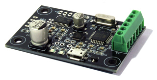
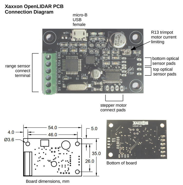
Initial PCB Wiring and Setup
NOTE: These instructions are only for custom sensor builds or repairs – the Xaxxon OpenLIDAR Sensor typically ships with these steps complete and the board ready to run.
Connection Diagram:

(click to enlarge)
Solder Optical Sensor

Solder the optical sensor OPB625 to either the OPT BOT or OPT TOP pads -if using the OPT BOT pads, the sensor should be mounted to the bottom of the board.
Connect Garmin Sensor
Connect the 6 leads from the Garmin LIDAR-Lite sensor to the corresponding screw terminals – read the Garmin manual to determine which colour wire goes where; note that this board always uses i2C instead of PWM, so the yellow ‘mode control’ wire goes to the ‘NC’ (not connected) terminal. See schematic for more info.
Solder Pins and Connect Motor
Solder the 4x male pin header into the J6 motor pads as indicated in the connection diagram — using the straight or angle pins supplied, solder to the top or bottom of the board depending on sensor configuration.
When plugging in the ROB-10551 motor, the motor plug should be oriented so the yellow lead is closest to the PCB mounting hole, and the black lead is closer to the center of the board.
Connect to PC and Set the Current Limiting Potentiometer
For this step the rest of your sensor should be fully assembled and you should have access to the R13 trimpot to adjust it with a small phillips screwdriver.
Connect the sensor to a PC with a USB cable, and use the Arduino IDE to connect to it — flash the firmware if necessary (use settings duemilanove/328P). Then open the serial monitor, set the baud rate to 115200 and line ending to NL/CR.
Enter the command ‘x’ to check if the board has the correct firmware properly installed — it should return “<id::xaxxonopenlidar>”.
Then enter the command ‘3’ to temporarily disable the host hearbeat check (by default the motor will be turned off if there is no serial input from a host PC after 10 seconds).
Turn the trimpot as far as it goes to the right/clockwise – NOTE: be gentle with the trimpot, it’s easy to turn it past its stops and permanently damage it. Then, enter the command ‘g’ into the serial terminal to start the motor turning. Nothing should happen, because you’ve disabled the current completely by turning the pot fully clockwise. Now, turn it left/counterclockwise a little bit (approx 5 degrees) to start the motor turning. Dial it in from there so it’s at the point where it just starts turning smoothly, and motor noise is at a minimum.
Press ‘s’ to stop the motor. You shouldn’t have to adjust this pot again, unless you switch to a host system that has a significantly different USB output voltage.


